These instructions apply to BricsCAD V20 Professional/Ultimate or later and describe how to load georeferenced MetroMap imagery using Web Map Service (WMS) or downloaded imagery from MetroMap.
Screen images shown below in these instructions are from a combination of BricsCAD V20 and V23.
Setting up a WMS Service
Before you start
You will need the below URL:
The following URL requires your API Key
https://api.metromap.com.au/ogc/key/{YOUR_API_KEY}/service?REQUEST=GetCapabilities
An API Key can be requested from either your Enterprise Admin or MetroMap Support.
Setup Steps
Follow these steps to set up BricsCAD WMS integration:
-
Save your CAD file before following actions.
-
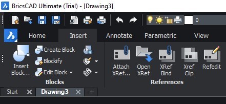
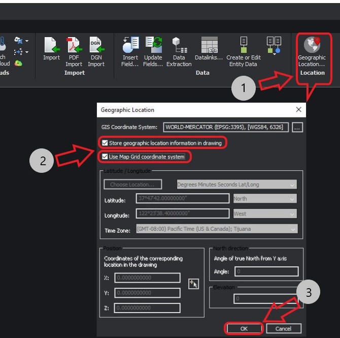
Click the Insert menu and select Geographic Location....
-
In the Geographic Location window,
- click ... button to set your preferred GIS Coordinate system
- check Store geographic location information in drawing option and Use Map Grip coordinate system option; then click OK.
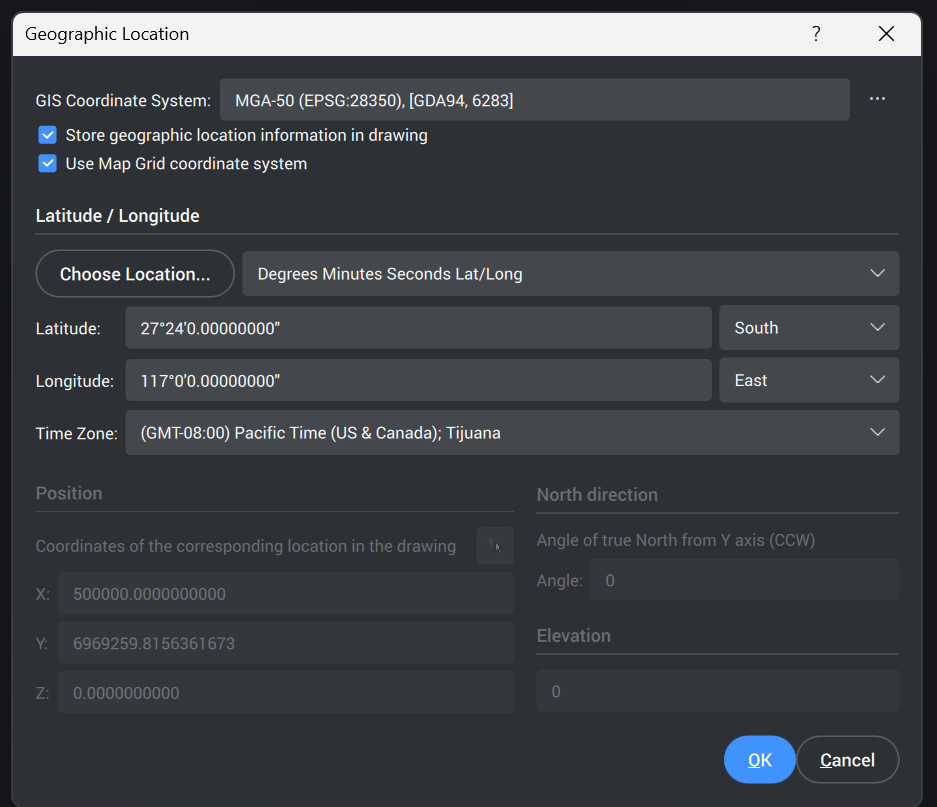
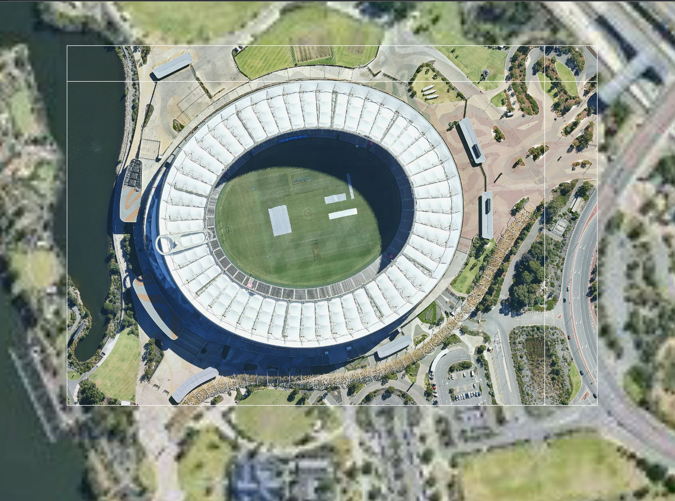
MGA-50 / GDA94 (EPSG:28350)was used in this particular example (Perth location).
Please note that MetroMap provides the following Coordinate Reference System through WMS service:- EPSG:4283
- EPSG:4326
- EPSG:3857
- EPSG:28349 - 28356
- EPSG:7849 - 7856
- EPSG:7844
- EPSG:3107
- EPSG:8059
It is not recommended to use Web Mercator (EPSG:3857) in BricsCAD
-
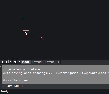
In the Command line area, type
MAPCONNECTthen hit Enter on keyboard.
-
In the Map Content window, name your connection in the Server URL field,
https://api.metromap.com.au/ogc/key/{YOUR_API_KEY}/service?REQUEST=GetCapabilitiesSelect
1.3.0as Server version then click Connect directly.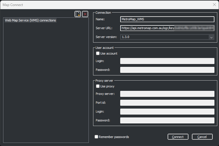
-
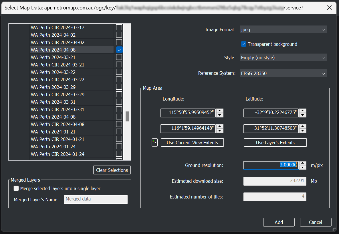
In Select Map Data window, choose your desired imagery layer on the left, then:
- select jpeg as Image Format;
- Select your prefered Reference System;
- Enter a reasonable value for Ground resolution so that the Estimated download size will be set below 500 Mb;
- then click Add.
-
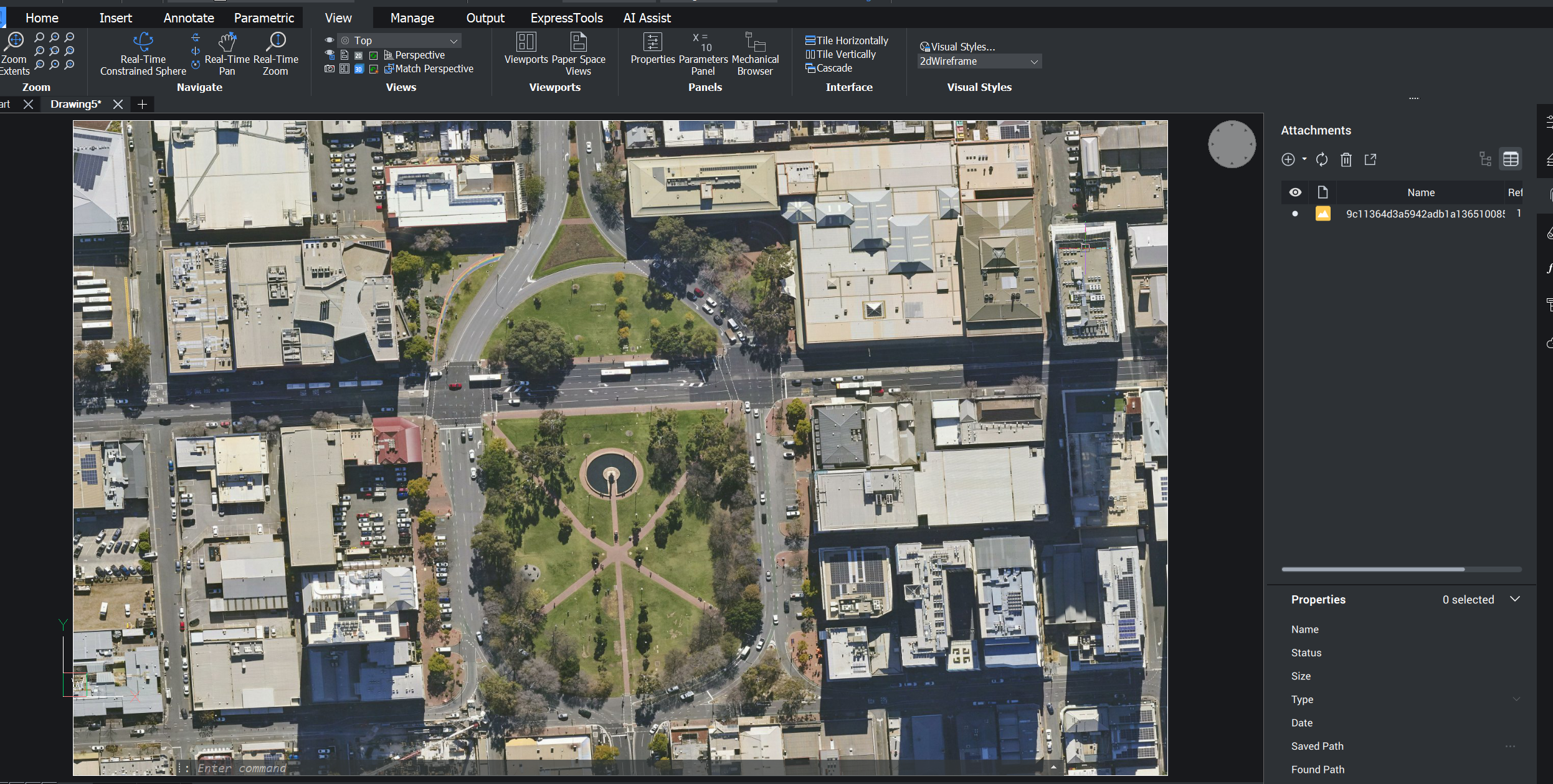
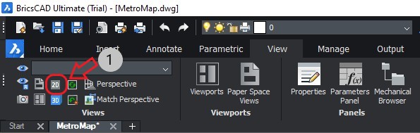
The imagery layer should have shown in the drawing area, if not, in the view menu, click the 2D button.
-
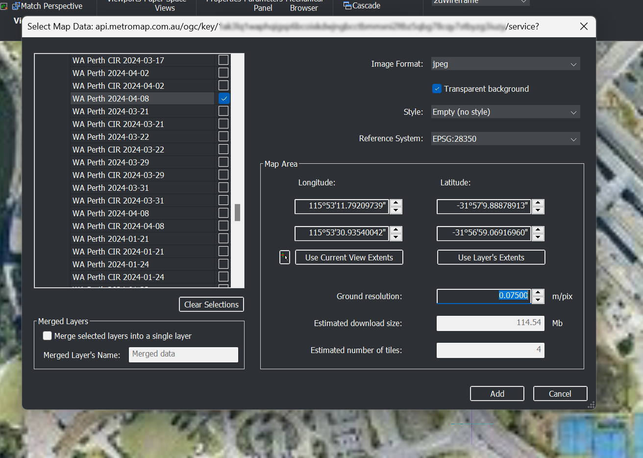
Move your display to a location that you want to closely inspect, then type
MAPCONNECTin the Command line area then hit Enter on keyboard; click connect directly. -
Choose the same imagery layer or a different layer on the left;
- choose the same Image Format and the same Reference System as in step 7;
- click the mouse icon next to 'Use Current View Extents' button and create a rectangle to choose your desired load area, or leave as the default value to load the whole layer area;
- reduce the value for Ground resolution to ensure you would have a clear view of the area of interest. It is recommended to set the value accordingly so that Estimated download size will be set around or below 900 Mb, otherwise the waiting time will be significant.
- Click Add.
-
The detailed imagery will show on the inspect area.
Loading Georeferenced Images
If you have used Clip It! tool or Download Image tool from MetroMap website and you want to project this image onto BricsCAD, the following steps will help you through.
Before you start
You can import JPG/JGW file pairs downloaded from the MetroMap into BricsCAD® V20 with the following instructions. Specifying or changing the map projection of the image is not supported, so ensure that your image is in the projection you want before importing it. Choose the matching map projection system especially when you have multiple georeferenced images loaded/to load into BricsCAD
Please note that our MetroMap system provide various projection systems.
For more introduction about Projection Systems and what MetroMap supports, please refer to Clip It!.
It is not recommended to use Web Mercator (EPSG:3857) in BricsCAD
Screen images shown below in these instructions are from BricsCAD® V20.
Setup Steps
-
Save your CAD file before the following actions.
-
Click the Insert menu and select Geographic Location....
-
In the Geographic Location window,
- click ... button to set your preferred GIS Coordinate system
- check Store geographic location information in drawing option and Use Map Grip coordinate system option; then click OK.
GDA2020 LL (EPSG:7844)was used in this particular example. For more information about Projection Systems, please refer to Clip It!. -
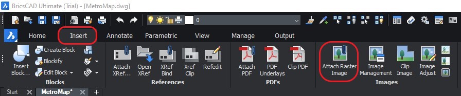
In the Insert menu, click Attach Raster Image, then select your preferred image.
-
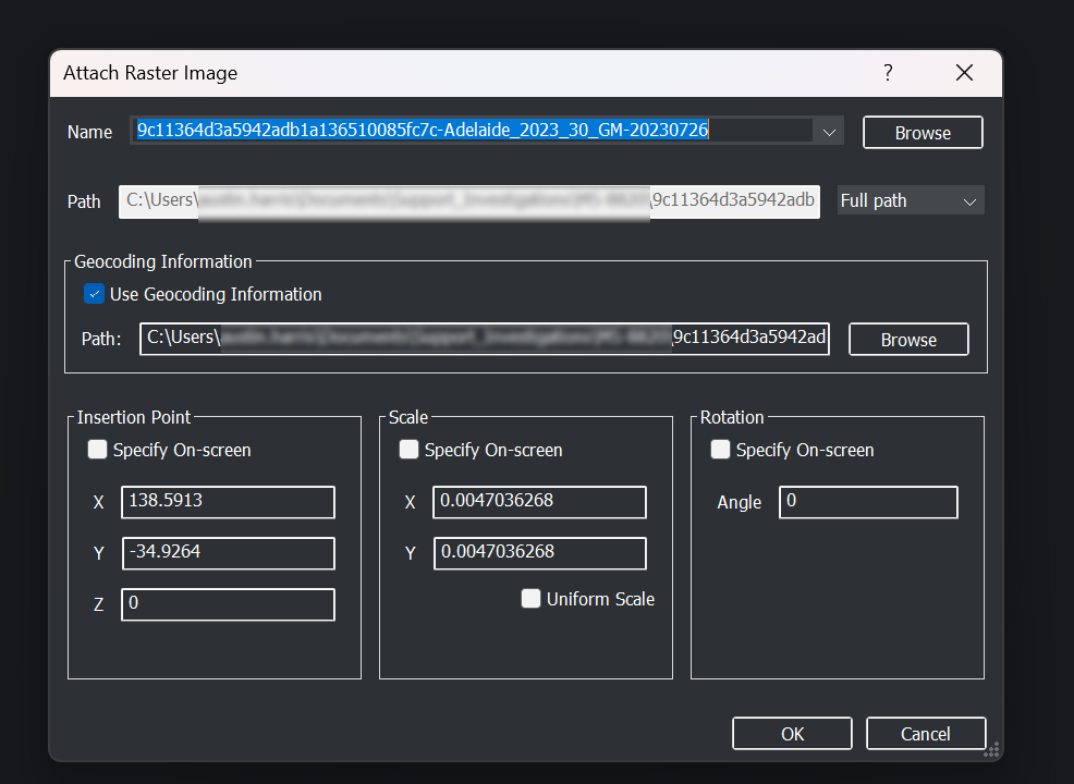
In Attach Raster Image window, tick the Use Geocoding Information checkbox, then click Browse to select the .jpw file. Then click OK.
-
Your image should now appear in the Model tab. If not, select Top view option in the drop down menu located in the View tab.
If you have extra images to import, please repeat Step 4 - 5. If your images are adjacent or overlap each other, they will be joined together.